|
|
|
Categories
|
|
Information
|
|
Featured Product
|
|
|
 |
|
|
There are currently no product reviews.
 ;
Thr Video Recorder i have is quiet Old and the Producer could Not help me. So i w as very glad to find an offer for the owners Manual for a very fair Price.a I obtained the original Manual very quick and I am happy to have it now.
 ;
The PDF copy was immediately available on download after the payment. However, I noticed that the document was in German, and Ihad to contact a German translator to get it translated it to English. The quality of document is legible can be used for my purpose.
;
The manual was complete and of great quality. Originally a tri-lingual file, I first received only one language. After a note to owners-manuals.com, I quickly received the remaining languages... Great service, definitely worth it.
;
Thank you for providing this manual and at low cost.
The Philips scope is of excellent quality, longevity and build and had a couple of faults
when it was passed to me. Having the CCT diagrams is a blessing.
I have fixed the problems and also modded the scope to my requirements.
I have built a 24v Li-Ion pack for portable use from old but good laptop batts.
it is working beautifully and I am well pleased. Keep up the good work Guys.
;
manual was very helpful in learning how to propery use my washer. I could not find this manual anywhere else.
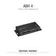
Introduction Thank you for choosing Harman Kardon®! The ABH 4 Expansion Hub that you have purchased will enable you to extend the capabilities of an A-BUS®based multiroom system to four or more rooms, with a Harman Kardon A-BUS/READY receiver as the control point. In applications in which you wish to add A-BUS connectivity to a receiver, preamplifier or surround processor that is not A-BUS/READY, a few simple connections to a multiroom or tape output will enable you to add the power and simplicity of A-BUS to your home. We strongly recommend that you carefully read this instruction sheet before installing your new ABH 4. It contains important information that will guide you step by step through the correct and safe installation of the unit. If you do not have experience installing in-wall electrical and telecommunications components, you are advised to consult with a qualified low-voltage contractor or custom installer. If you have any questions about this product, its installation or its operation, please contact your retailer or custom installer. He or she is your best source of product information. Designed for simple installation by a custom installer or advanced do-it-yourself hobbyist, the ABH 4 will add to your listening pleasure by distributing sound throughout your home with the level of performance and product design elegance for which Harman Kardon has been famous for more than fifty years. Features � Simple connection to any A-BUS/READY Harman Kardon receiver � Easy interface with existing audio/video receivers, preamplifiers or processors to add A-BUS capability for multiroom systems with only a single Category 5 cable run to each remote module � Designed for easy mounting on wire back-boards, or for shelf placement IMPORTANT SAFETY AND INSTALLATION INFORMATION! Wire Separations Remote control wiring systems must be installed to minimize the possibility of accidental contact with hazardous power and lighting wiring. Never place remote control wiring near bare power wires or lightning rods, antennas, transformers, steam or hot water pipes, or heating ducts. Never place remote control wire in any conduit, box, channel, duct or other enclosure containing power or lighting circuits of any type. Always provide adequate separation of remote control wiring and other electrical wiring according to code. When in doubt about separation distances, the �Rule of Sixes� can be used. This rule requires 6 feet of separation between remote control wiring and open high-voltage wiring, lightning grounding wire or grounding rods. It requires 6 inches of separation from all other highvoltage wiring, unless in conduit. Cutting and Drilling Always observe trade safety rules for concealed wiring. Be extremely careful not to cut through or drill into concealed wiring or pipes. Make a small inspection opening before cutting or drilling.
Additional Installation Information Common wire-splicing techniques may cause the wire to break, resulting in poor circuit integrity. This can cause interference and result in poor system performance. Dust or dirt can cause special problems on wiring contacts. Be sure all contacts are clean and that all parts are installed correctly to protect them from dust and dirt. Your new Harman Kardon ABH 4 A-BUS Expansion Hub has been customdesigned for use with A-BUS products. Do not connect the RJ-45 jacks to any other device. Make sure to follow all instructions when preparing wiring for use with the ABH 4 Expansion Hub and associated equipment. Failure to do so may result in a potential safety hazard, including possible danger to persons and/or equipment. If you will be running RJ-45 cable through a ventilation plenum, remember to use plenum-rated cable to comply with NEC and other safety requirements. Failure to do so may result in a potential fire or safety hazard. If you have any doubt about your ability to work with electrical and telecommunications wiring, you are advised to hire a professional licensed electrician or custom installer to install this product. Installation Planning When installed, the ABH 4 may be placed flat on a shelf or mounted to a wire back-board using standard wood screws and the keyhole notches on the outer edge of the ABH 4. The unit�s power supply must be placed on a shelf and should not be attached to a back-board. When planning an installation, remember to allow sufficient clearance for all wires and connectors that will be attached to the ABH 4 so that severe angle bends of connecting cables are avoided. The wiring used to connect the ABH 4 to the A-BUS/READY receiver and A-BUS modules in remote rooms may be Category 5 or 5e wiring. Be certain that any specific safety rating requirements for riser or plenum wiring are taken into account, if needed. The speaker wiring should also be in-wall-rated as required, and may not exceed 14 AWG. To simplify wiring, you may wish to use two pairs of (4x14) CL-3-rated in-wall wiring and run a single cable from the ABH 4 to both locations. One pair will be used to connect the first speaker and the other will continue to the second speaker. What Is Included
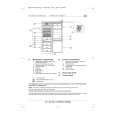
Typographical Conventions To help you use this manual, the following typographical conventions are used to identify the various parts of the product. ¡ (number in a circle) Indicates a connection point on the side edges of the ABH 4. å (letter in a circle) Indicates an LED indicator on the top face of the ABH 4. Top-Edge Connections ¡ Status Input: When the ABH 4 is used in the stand-alone mode with a non-A-BUS/READY source or receiver, an optional 12-volt DC power source may be attached to this jack to keep the A-BUS system active. � Power Input: Connect the small mini plug at the end of the ABH 4 power supply to this jack. £ Audio Inputs: When the ABH 4 is used in the stand-alone mode to create an A-BUS system using a receiver that is not A-BUS/READY, connect the right and left audio outputs from the feed source to these input jacks. The source may be a single product such as a tuner or CD player, or it may be the Tape outputs or Multiroom outputs of a receiver. Note that these inputs are connected to Music Sense circuitry that will automatically turn on all A-BUS modules connected to the ABH 4 when an audio signal is present, and turn them off 30 seconds after the audio signal stops. ¢ Expansion In Jack: This jack connects to the device that is providing the A-BUS system source that feeds the A-BUS modules used with this ABH 4. In most applications, the connection will be to the A-BUS output on a Harman Kardon A-BUS/READY receiver, although the input may also come from the Expansion Out Jack � of another ABH 4 when multiple hubs are in use. In all cases, the connection should be made using a standard TIA 568A RJ-45 jumper cable. � Expansion Out Jack: If you are using more than one ABH 4 in your system to add additional rooms, connect one end of a jumper cable with RJ-45 connectors to this jack. Connect the other end of the jumper cable to the Expansion In Jack ¢ on the next ABH 4. Bottom-Edge Connections § Local IR Input Terminals: When the ABH 4 is used with a source product other than an A-BUS/READY receiver, these terminals allow you to connect a compatible, optional IR receiver/sensor to receive infrared remote commands for the control of source components in a room where there is no A-BUS module. IR commands received by the sensor will be retransmitted to the IR Emitter Jacks ¶ for use with optional IR emitters. Follow the instructions packed with the IR receiver/sensor for the proper connections to the terminals here. To connect wires from the sensor, unscrew the retaining screw on the appropriate terminal until wire clamp retracts into the bottom of the terminal block. Insert the wires following the instructions in Step Seven on the other side of this sheet, and tighten the screw until the clamp secures the wire so that it does not fall out. ¶ IR Emitter Jacks: These jacks route the IR signals that are received either
INSTALLATION AND CONNECTION Important Safety Note: Before beginning the installation process, make certain that all electronics products in the system are turned off and disconnected from their A/V power connection. This avoids the possibility of accidental activation that could possibly damage the equipment or cause personal injury. Do not turn on the equipment until instructed. The ABH 4 may be used in two modes of operation. The installation process will vary according to which option you select. � When used in conjunction with an A-BUS/READY Harman Kardon receiver, the ABH 4 provides the power that enables up to four remote rooms to be equipped with A-BUS modules such as the Harman Kardon AB 1, with more room installations possible through the use of additional ABH 4 hubs. � The ABH 4 may also be used with any receiver, preamplifier or surround processor that that has a �tape� or �multiroom� output to send the selected source to A-BUS modules installed in remote rooms. Alternatively, a Tuner or CD player may be connected to the ABH 4 to create a one-source multiroom audio system. Mounting the ABH 4 (optional) Before making any connections to the ABH 4, read the instructions below and carefully plan the placement of any wiring that may be required. The ABH 4 may be mounted on a wall using the screw slots provided on the sides of the unit, or it may simply be placed on any flat surface. � To mount the ABH 4 to a wall, first place the unit against the surface to which it will be mounted, and make certain that there is sufficient clearance at all sides for any cables that will be attached and that they are able to reach their destination. � Although the ABH 4 is relatively light, make certain that the wall surface is able to support the ABH 4. � While holding the ABH 4 to the wall, trace the outline of the slots on the �wings� at the left and right side of the ABH to the wall.
� Drill a pilot hole and install an anchor or retaining socket sufficient to accommodate a #10 pan-head Phillips-type wood screw that is at least 1 inch long at each side, under the circular part of the tracing. If you have any questions or doubt about the ability of the wall surface to properly support the weight of the ABH 4, consult a properly trained installer before proceeding. � When the anchor is installed, place a screw through the slot on either side of the ABH 4 and then tighten the screw into the anchor until it is almost completely secured. � Slip the ABH 4 so that it slides down the keyhole notch of the slot and then tighten it securely to the wall. Connections to an A-BUS/READY Receiver Step One: Connect the ABH 4 to the Receiver Using the RJ-45 jumper cable supplied with the ABH 4, connect one end to the Expansion In Jack ¢ on the ABH 4 and the other end to the A-BUS/READY jack on the rear panel of your Harman Kardon receiver. Step Two: Connect the A-BUS Modules Connect the RJ-45 jacks on the Cat. 5 cabling that runs to the remote room modules to the A-BUS Outputs � on the ABH 4. Make certain that the connector is wired in accordance with the standard TIA 568A color-coding. Connect the A-BUS modules in the remote rooms to the Cat. 5 cable in accordance with the instructions for the module. Step Three: Connect the AC Power Supply Connect the AC Power Supply furnished with the ABH 4 to the Power Input �. Plug the AC power cord into the socket on the Power Supply. Do not connect the power cord to an AC outlet at this time. Optional Step Four: Multiple ABH 4 Connections If you are using more than one ABH 4 in a system, connect the Expansion Out Jack � to the Expansion In Jack ¢ on another ABH 4, using the RJ-45 jumper cable supplied with the second ABH 4. Then, follow steps two and three, as shown above.
¡
�
£
¢�
Your ABH 4 should be packed with the following items. If any of the below are missing, please contact Harman Kardon customer service. � ABH 4 Expansion Hub � Power Supply � AC Power Cord � RJ-45 Connection Jumper Cable
When using an A-BUS/READY product, use the supplied RJ-45 jumper cable to connect the A-BUS jack on the receiver to the �Expansion In� jack on the ABH 4.
¡
�
£
¢�
å � ç
by the remote sensor in an A-BUS module such as Harman Kardon�s AB 1 or from an optional IR receiver connected to the Local IR Input Terminals § to optional remote IR emitters. These emitters should be placed over the IR receiver in the source components to be controlled in accordance with their manufacturer�s instructions. This enables a remote control where an A-BUS module is installed to control source components such as a CD or DVD player. � A-BUS Outputs: These jacks are the communications link between the remote A-BUS modules and the ABH 4, carrying audio signals and power to the A-BUS modules, and IR commands from the A-BUS modules to the ABH 4 and products connected to it. Connect a cable from each remote A-BUS module to these outputs using standard RJ-45 connectors with cabling wired in compliance with the TIA 568A standard. LED Indicators å Status Indicator: This LED will light when the ABH 4 is activated. In most cases, it will light when a Harman Kardon A-BUS/READY receiver connected to the ABH 4 is turned on. When the ABH 4 is used with non-A-BUS/READY products, the Status Indicator will light when an audio signal is present at the Audio Inputs £ or when a DC power source is connected to the Status Input ¡. The Status Indicator will go out 30 seconds after the power or audio source is removed. � Power Indicator: This LED will light to indicate that the ABH 4 is connected to a power source that enables the remote modules and the infrared relay system to operate. This power source may be either a connection to an A-BUS/READY product, the ABH 4�s power supply or through a connection to another ABH 4. Note that the ABH 4�s external power supply must be connected in order for it to power multiple remote modules. ç IR Indicator: This LED will flash to confirm that an IR signal is being passed through the ABH 4. This signal may originate from a remote A-BUS module or from an optional remote sensor attached to the Local IR Input Terminals §.
FL 8385
ABH 4 power supply
¡
�
£
¢
�
å � ç
Source component with optional IR emitter placed over IR sensor
1 4 2 5 3
DISKSKIP
PLAY/PAUSE STOP
��
SEARCH
��
���
SKIP
���
�
¶
§
Power
Phones
Phones Level
å � ç
31
240
�
¶
§
Optional AB 1 A-BUS modules connected by Cat. 5 cabling
DVD player or other source component with connection to compatible IR input jack
|
|
|
> |
|